ออกแบบระบบอากาศอัดสำหรับ CIP วาล์ว โรงงาน Beverage: คู่มือคำนวณขนาด Actuator, NL/Cycle และ Pressure Drop ให้ครบ
- วงจร CIP ต้องการอากาศอัดแรงดันสูงกว่า plant header 0.5–1.0 bar เพื่อเปิด-ปิดวาล์วโดยไม่สะดุด — การใช้ header เดียวกับสายการผลิตทำให้เกิด pressure dip ขณะ cycle สูงสุด
- สูตรคำนวณ NL/cycle ต่อ actuator รวมกับ cycle rate จะให้ peak flow demand ที่ใช้ sizing ถัง receiver และ compressor ได้อย่างแม่นยำ
- แหล่งจ่ายอากาศแยก Class 0 สำหรับ CIP โดยเฉพาะ (ไม่ใช่ header ทั่วไป) ป้องกัน contamination event ที่เป็น nonconformity ใน ISO 22000 audit
วงจร Clean-in-Place (CIP) ในโรงงาน beverage — ตั้งแต่ tank ล้าง aseptic filling จนถึง plate heat exchanger — ขับเคลื่อนด้วย pneumatic actuator หลายสิบตัว ที่เปิด-ปิดพร้อมกันในช่วง purge และ rinse cycle กระบวนการนี้สร้าง peak air demand ที่สูงและสั้น ต่างจาก process air แบบ steady-state ทั่วไป วิศวกรที่ออกแบบหรือตรวจสอบ CIP air circuit จำเป็นต้องคำนวณ NL ต่อ cycle ต่อ actuator, flow rate สูงสุด (Nm³/h) ที่ valve bank, และ pressure drop ตลอด distribution line ก่อนจะเลือกขนาด receiver tank และ compressor ที่เหมาะสม — บทความนี้แสดงวิธีคำนวณทีละขั้นตอน พร้อมอธิบายว่าทำไม AERZEN จึงแนะนำให้แยก ISO 8573-1 Class 0 oil-free air supply เฉพาะ CIP circuit ออกจาก plant general header
ทำความเข้าใจ CIP Air Demand: Duty Cycle ไม่เหมือน Process Air
กระบวนการ CIP ในโรงงาน beverage เช่น brewery, dairy UHT หรือ juice aseptic filler ประกอบด้วย sequence หลายขั้นตอน: pre-rinse, caustic wash, acid rinse, final water rinse และในระบบ aseptic อาจมี steam sterilization ตาม ในแต่ละขั้นตอน PLC จะส่งสัญญาณเปิด-ปิด valve หลายตัวพร้อมกัน โดย air actuator รับแรงดันอากาศเป็น power source สำหรับ travel stroke
ความแตกต่างสำคัญจาก process air ทั่วไปคือ CIP air มีลักษณะ intermittent high-peak demand — ในช่วง valve actuation burst (3–8 วินาที) ทุกตัวใน bank อาจเปิดพร้อมกัน ทำให้ flow rate พุ่งสูงแล้วกลับสู่ standby แทบเป็นศูนย์ทันที การออกแบบระบบด้วย steady-state flow assumption จะได้ขนาด compressor ที่ oversize อย่างมีนัยสำคัญ หรือได้ receiver ที่เล็กเกินไปจนแรงดันดรอประหว่าง burst
AERZEN จำแนก CIP pneumatic load ออกจาก “process instrument air” เพราะ duty cycle ต่างกัน: instrument air = quasi-continuous low-flow; CIP actuator air = burst high-flow ทุก cycle. การ share header เดียวกันจะทำให้ pressure dip กระทบ instrument signal ในช่วง CIP burst และอาจ trigger false alarm บน PLC
วิธีคำนวณ NL/Cycle ต่อ Actuator และ Peak Flow ที่ Valve Bank
Step 1 — คำนวณ NL ต่อ stroke ต่อ actuator หนึ่งตัว
สำหรับ double-acting pneumatic actuator (หมุน 90° ขับ butterfly valve) ปริมาณอากาศต่อ stroke คำนวณจาก cylinder geometry:
V_stroke (L) = (π/4) × D² × L_stroke × (P_supply / P_atm)
โดย: D = bore diameter ของ cylinder (m) | L_stroke = stroke length (m) | P_supply = supply pressure (bar abs) | P_atm = 1.013 bar abs
ตัวอย่าง: butterfly valve DN100 ใช้ double-acting scotch-yoke actuator — bore 80 mm, stroke 52 mm, supply 6 bar gauge (7.013 bar abs):
V = (π/4) × 0.08² × 0.052 × (7.013/1.013) = 0.000261 × 6.92 ≈ 0.00181 m³ = 1.81 NL/stroke
actuator double-acting: เปิด + ปิด = 2 × 1.81 = 3.62 NL/cycle
Step 2 — รวม NL/cycle ของทุก actuator ใน valve bank
CIP valve bank โดยทั่วไปในสาย beverage ขนาดกลางมี actuator 8–24 ตัว ไม่ใช่ทุกตัวเปิดพร้อมกัน — PLC logic กำหนด simultaneous actuation group ตาม sequence ให้ระบุ group ที่ใช้ air สูงสุด (worst-case group) เพื่อ sizing:
| Valve Group | จำนวน Actuator | NL/cycle ต่อตัว (ตัวอย่าง) | รวม NL/cycle | หมายเหตุ |
|---|---|---|---|---|
| Group A — tank inlet | 4 | 3.62 | 14.5 | DN100 butterfly |
| Group B — CIP return | 4 | 2.84 | 11.4 | DN80 butterfly |
| Group C — bypass divert | 3 | 1.92 | 5.8 | DN50 ball valve |
| Group D — drain | 2 | 1.44 | 2.9 | DN40 butterfly |
| Worst-case burst (Groups A+B) | 8 | — | 25.9 NL | peak sizing basis |
Step 3 — แปลง NL/cycle เป็น Peak Flow Rate (Nm³/h)
Q_peak (Nm³/h) = V_total (NL) × 3.6 / t_stroke (s)
โดย: V_total = NL demand ของ worst-case group | t_stroke = stroke duration (วินาที)
ตัวอย่าง: 25.9 NL ใน 5 วินาที = 25.9 × 3.6 / 5 = 18.6 Nm³/h peak
หากมี CIP cycle 4 รอบต่อวัน รวม 10 burst/cycle: ปริมาณรวม = 25.9 NL × 10 × 4 = 1,036 NL/วัน (~1.04 Nm³/วัน) — ปริมาณต่ำ แต่ peak flow 18.6 Nm³/h เป็นตัวกำหนด compressor และ receiver size ไม่ใช่ค่าเฉลี่ยรายวัน
Pressure Drop ตลอด CIP Line: คำนวณให้ถึง Valve Bank
แรงดันที่ valve bank ต้องเพียงพอสำหรับ actuator spring return + safety margin ทั้งหมด โดยปกติกำหนด minimum working pressure ที่ valve bank = 5.5–6.0 bar gauge สำหรับ standard pneumatic actuator ที่ใช้ spring range 3–5 bar วิศวกรต้องคำนวณย้อนกลับจาก valve bank ขึ้นไปถึง receiver outlet เพื่อกำหนด set pressure ของ compressor:
| Component | ΔP (bar) | หมายเหตุ |
|---|---|---|
| Pipe friction loss (30 m, DN25, Nm³/h 18.6) | 0.08 | คำนวณด้วย Darcy-Weisbach; ค่า f ~ 0.025 |
| Filter/regulator (coalescing filter + regulator) | 0.15 | dirty filter scenario — plan 0.15 bar |
| Elbow 90° × 4 + tee × 2 (equivalent length) | 0.05 | fitting losses (Le/D table) |
| Solenoid valve pilot pressure loss | 0.10 | ISO 5599 port size ควร verify กับ valve datasheet |
| รวม ΔP | 0.38 bar | margin เพิ่ม 0.2 bar → set receiver ที่ 6.5 bar g |
อย่าใช้ plant header ที่ maintain ที่ 7 bar g สำหรับ process air เป็น reference โดยตรง เพราะขณะที่ CIP burst demand สูงสุด เครื่องอัดอากาศหลักอาจอยู่ใน load-unload cycle ทำให้ header pressure ดรอปไปต่ำกว่า 6.5 bar เป็นเวลาหลายวินาที — actuator ที่ได้รับแรงดันน้อยกว่า spec จะปิดไม่สุด เกิด valve chatter และ CIP liquid contamination ย้อนเข้าสาย instrument air ได้
Sizing Receiver Tank: ลด Peak Demand โดยไม่ต้อง Oversize Compressor
Receiver tank ทำหน้าที่เป็น buffer — จ่าย air burst ที่ compressor ไม่สามารถตอบสนองได้ทันเนื่องจาก ramp-up time สูตรคำนวณขนาด receiver สำหรับ CIP application:
V_R (L) = (Q_peak × t_stroke × P_atm) / (P_max - P_min)
โดย: Q_peak = peak demand (L/s ที่ atmospheric) | t_stroke = burst duration (s) | P_max - P_min = allowable pressure band ของ receiver (bar)
ตัวอย่าง: Q_peak = 18.6 Nm³/h = 5.17 NL/s; t_stroke = 5 s; P_band = 6.5–5.5 = 1.0 bar:
V_R = (5.17 × 5 × 1.013) / 1.0 = 26.2 L minimum
ปฏิบัติ: เลือก receiver ขนาดถัดไปที่มีขาย — 50 L receiver สำหรับ CIP circuit นี้ เพียงพอและไม่ oversize จน footprint ใหญ่เกินไป
สำหรับโรงงาน beverage ขนาดกลาง (production 5,000–15,000 ลิตร/วัน) ที่มี CIP valve bank 2–3 สาย แต่ละสายมี receiver 50–100 L แยกกัน และใช้ compressor AERZEN TVO (oil-free screw compressor) ขนาด 7–15 kW เป็น dedicated supply — รูปแบบนี้ได้รับการยืนยันในหลาย installation ของ AERZEN ในภาคตะวันออก
ทำไมต้องแยก Class 0 Supply สำหรับ CIP โดยเฉพาะ
CIP circuit ใน beverage plant มีความเสี่ยงพิเศษที่ process air ทั่วไปไม่มี: อากาศอัดสัมผัสโดยตรงกับพื้นผิวที่จะสัมผัสอาหาร ในขั้นตอน air purge หลัง rinse final — หากอากาศมี oil aerosol ปนเปื้อน (Class 1 หรือต่ำกว่า) oil จะสะสมบน valve seat และท่อ แล้วปนเปื้อนเข้า batch ถัดไป
| มิติ | Shared Plant Header | Dedicated Class 0 Supply |
|---|---|---|
| Oil contamination risk | สูง — header มักเป็น Class 1–2; filter ชำรุดได้โดยไม่ตรวจพบ | ต่ำมาก — compressor oil-free ตั้งแต่ต้น; ไม่มี oil ใน compression stage |
| Pressure stability ระหว่าง CIP burst | ไม่แน่นอน — ขึ้นกับ load ของ header ทั้งหมด | ควบคุมได้ — receiver + regulator อิสระ |
| ISO 22000 / FSSC 22000 audit | ต้องพิสูจน์ว่า filter chain ทำงาน — auditor ตรวจ change log | พิสูจน์ง่าย — TÜV certificate + oil-mist test log ที่ AERZEN จัดส่งพร้อมเครื่อง |
| Capital cost | ต่ำ (ใช้ header เดิม) | CAPEX เพิ่ม — แต่ rental model ของ AERZEN ไม่มี CAPEX |
| Downtime risk | CIP หยุดถ้า plant compressor down | CIP air อิสระจาก plant; production air down ≠ CIP down |
| EHEDG guideline alignment | ไม่สอดคล้อง EHEDG Doc. No. 32 — ต้องการ dedicated oil-free air point ที่จุดสัมผัสอาหาร | สอดคล้อง EHEDG Doc. No. 32 (Hygienic Engineering of Compressed Air Systems) |
AERZEN TVO oil-free screw compressor ผลิตอากาศปลอดน้ำมัน 100% ตั้งแต่ compression stage — ไม่มี oil ในห้องอัด ไม่ต้องพึ่ง coalescing filter chain เพียงอย่างเดียว ซึ่งเป็นความแตกต่างที่สำคัญจาก oil-lubricated compressor ที่ติด oil-removal filter ท้าย สำหรับ CIP circuit ที่ต้องการ documentary evidence สำหรับ ISO 22000 audit วิธีนี้ช่วยลดภาระการตรวจสอบ filter condition log อย่างมีนัยสำคัญ
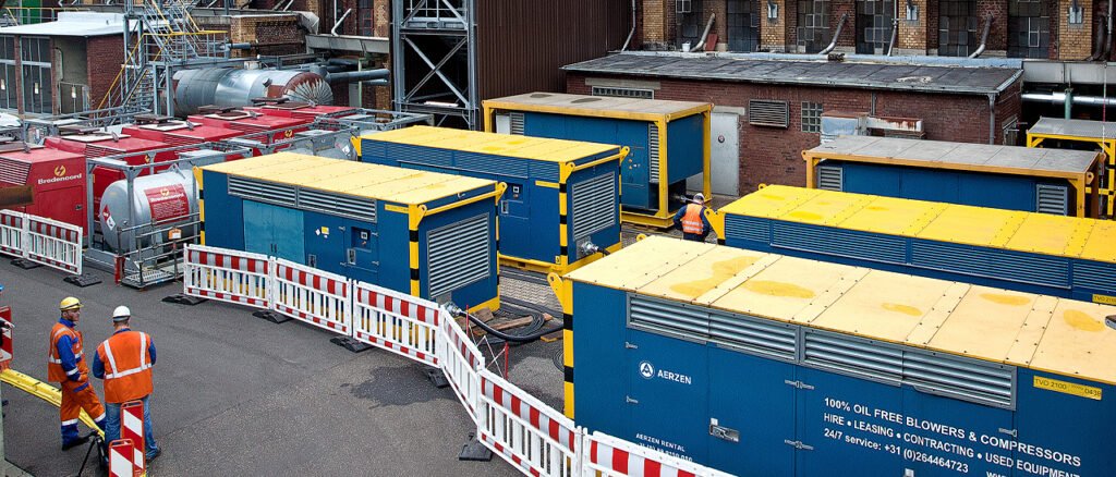
สำหรับโรงงานที่ต้องการทดสอบ concept โดยไม่ลงทุน CAPEX — AERZEN Rental Thailand ให้เช่า TVO oil-free screw compressor พร้อม TÜV Rheinland certificate และ oil-mist zero-reading test log ส่งมอบภายใน 24–48 ชั่วโมง ทีมวิศวกรสามารถ size ระบบตามข้อมูลที่คำนวณในบทความนี้แล้วส่งมาขอใบเสนอราคาได้เลย
คำถามที่พบบ่อย (FAQ)
CIP valve bank ขนาดเล็ก (4–6 actuator) จำเป็นต้องมี dedicated compressor หรือใช้ receiver + filter ก็พอ?
สำหรับ valve bank ขนาดเล็กที่มี peak demand ต่ำกว่า 5 Nm³/h ระบบ filter chain + receiver ขนาด 100 L ต่อกับ plant header Class 0 อาจเพียงพอในทางเทคนิค แต่ความเสี่ยงคือ filter ชำรุดหรือ saturate โดยไม่มีการเตือน ส่วนใหญ่ผู้ออกแบบที่ผ่านการ audit ISO 22000 แล้วหลายรอบจะเลือก dedicated supply เพราะการพิสูจน์ Class 0 ง่ายกว่าและลด audit burden
ถ้าใช้ spring-return actuator (single-acting) สูตรคำนวณ NL/cycle เปลี่ยนไปอย่างไร?
Single-acting actuator ใช้ air เฉพาะ stroke เดียว (open หรือ close ขึ้นกับ fail-safe direction) — V_stroke คำนวณเหมือนเดิม แต่คูณด้วย 1 แทน 2 NL/cycle จะลดลงครึ่งหนึ่งเมื่อเทียบกับ double-acting ขนาดเท่ากัน อย่างไรก็ตามต้องตรวจสอบ spring return force ด้วย เพราะ spring preload สูงอาจต้องการ supply pressure สูงขึ้น ทำให้ได้ NL/stroke สูงกว่าที่คาด
ISO 8573-1 Class 0 กับ Class 1 ต่างกันอย่างไรในมุม CIP contamination risk?
Class 1 อนุญาตให้มี oil aerosol ≤ 0.01 mg/m³ — ซึ่งฟังดูน้อยมาก แต่ใน CIP circuit ที่ purge air สัมผัสพื้นผิว aseptic โดยตรง oil ระดับนี้จะสะสมเป็น biofilm base ที่ทำความสะอาดยากและเป็น contamination pathway ที่ auditor ISO 22000 ระบุว่าเป็น hazard Class 0 กำหนดว่า “no detectable oil” ซึ่งหมายความว่าต้องใช้ oil-free compression source ไม่ใช่เพียงแค่ filter-based purification
ระหว่าง TVO screw compressor กับ BVO blower — อะไรเหมาะกับ CIP air supply?
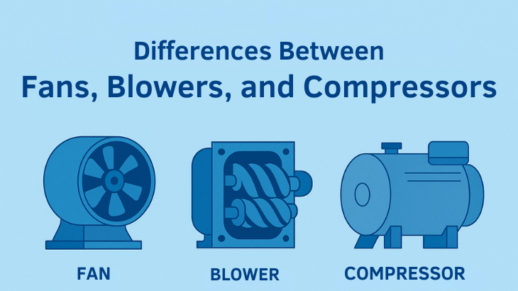
CIP actuator ต้องการแรงดัน 5.5–7 bar gauge ซึ่งอยู่นอกขอบเขตของ BVO positive displacement blower (pressure range 0.3–1.0 bar gauge) TVO oil-free screw compressor ที่ AERZEN ให้เช่ามี pressure range 6–13 bar เหมาะกับ CIP pneumatic actuator โดยตรง BVO เหมาะกับงาน aeration, fermentation air หรือ pneumatic conveying ที่ต้องการ low pressure high flow
ต้องเตรียมเอกสารอะไรบ้างสำหรับ auditor เมื่อใช้ AERZEN TVO เป็น CIP air supply?
AERZEN จัดส่งพร้อม: (1) TÜV Rheinland certificate ระบุ oil-free classification, (2) oil-mist zero-reading test log วันที่ส่งมอบ, (3) P&ID ของ air circuit พร้อม instrument tag, (4) datasheet ของ compressor series ระบุ ISO 8573-1 Class 0 compliance ทีมวิศวกร AERZEN สามารถจัดทำ HACCP air-supply checklist เพิ่มเติมตามคำขอ เอกสารชุดนี้ตอบได้ครบ audit evidence ที่ auditor ISO 22000 / FSSC 22000 ต้องการ
ขอใบเสนอราคา TVO Oil-Free Air สำหรับ CIP Circuit
ทีมวิศวกร AERZEN Rental Thailand ช่วย verify การคำนวณ NL/cycle, sizing receiver และ pressure drop ให้ฟรี — พร้อม TÜV certificate + oil-mist log ส่งมอบภายใน 24–48 ชั่วโมง

✍️ เกี่ยวกับผู้เขียน
ภราดร วรรณสังข์ (Paradorn Wannasung)
Marketing Communication Specialist · นิเทศศาสตรมหาบัณฑิต (การสื่อสารการตลาดและแบรนด์)
ภราดร (Paradorn) เป็นผู้ดูแลด้านการสื่อสารการตลาดของ AERZEN Rental Thailand จบนิเทศศาสตรมหาบัณฑิต (การสื่อสารการตลาดและแบรนด์) เชี่ยวชาญด้านอุตสาหกรรม B2B ในประเทศไทย มีประสบการณ์การสร้างแบรนด์และคอนเทนต์ในกลุ่มอุตสาหกรรมของไทย
ติดต่อ: pwa@aerzenrental.com · LinkedIn
บทความที่เกี่ยวข้อง

หัวข้อหลัก: อากาศอัดออยล์ฟรีสำหรับโรงงานอาหารและเครื่องดื่ม