
By Paradorn Wannasung · Master’s in Marketing Communication · AERZEN Rental Thailand
Introduction: Why Failure Modes Matter Before the Trip
A blower that trips unexpectedly costs more than the repair bill. In continuous-process industries — food, pharmaceutical, wastewater, pneumatic conveying — an unplanned stop cascades: batch loss, line stoppage, regulatory non-compliance, emergency labor. Experienced maintenance engineers do not wait for a trip. They read the machine.
This catalog documents the seven failure modes most frequently observed in industrial Roots blowers and rotary screw blowers. For each mode, we cover: the physical root cause, the early warning signals, the diagnostic approach, and the corrective action hierarchy — from field adjustment to rental swap-out.
As AERZEN has built rotating machinery since 1864, the failure patterns described here reflect more than 160 years of field engineering knowledge, validated against modern ISO monitoring standards.
Failure Mode 1: Bearing Wear — Progressive
Root Cause
Anti-friction bearings (deep-groove ball bearing or cylindrical roller bearing) degrade under cumulative load cycles, thermal cycling, and lubricant degradation. In Roots blowers, both the timing gear bearing and the rotor bearing are load points. Contaminated oil (water ingress, particulates) accelerates surface fatigue.
Early Warning Signals
- Vibration amplitude increase — particularly at bearing defect frequency (BPFO, BPFI, BSF) detectable by FFT analysis
- Discharge temperature trend upward without change in process conditions
- Bearing housing temperature 10°C above baseline (measured by contact thermometer or IR gun)
- Acoustic emission (AE) — crackling signature in ultrasound monitoring
Diagnostic Method
- Mount accelerometer on bearing housing (radial direction)
- Acquire time-domain waveform and FFT spectrum at operating speed
- Calculate BPFO/BPFI from bearing geometry — compare to spectrum peaks
- Trend monthly; plot envelope spectrum for inner/outer race signature
Reference standard: ISO 10816-3:2009, “Mechanical vibration — Evaluation of machine vibration by measurements on non-rotating parts — Part 3: Industrial machines with nominal power above 15 kW.” Available: https://www.iso.org/standard/28190.html — [verified 2026-06-12]
Corrective Action Hierarchy
- Level 1 (Green): Increase vibration monitoring frequency to weekly
- Level 2 (Yellow): Schedule bearing replacement at next planned shutdown
- Level 3 (Red): Isolate unit immediately; deploy rental standby; replace bearing
Failure Mode 2: Shaft Seal Leakage — Oil Migration to Air Stream
Root Cause
In oil-lubricated gear Roots blowers, shaft seals (labyrinth or lip seal) separate the gear/bearing cavity from the compression space. Seal degradation — from thermal cycling, incorrect installation, or particulate scoring — allows gear oil to migrate into the air stream. This is a critical failure for food, pharma, and process applications requiring oil-free air per ISO 8573-1.
Early Warning Signals
- Oil aerosol mist at outlet or discharge piping
- Oil film visible on downstream filter element (oil carryover test paper)
- Downstream ISO 8573-2 oil concentration test exceeds Class limit
- Increased oil consumption in gearbox (top-up frequency rises)
Diagnostic Method
- Install oil carryover test paper downstream of blower
- Conduct ISO 8573-2:2018 oil aerosol measurement — collect sample, weigh using gravimetric method
- Compare against ISO 8573-1 Class requirement of your process (Class 0 = user-defined level; Class 1 = ≤0.01 mg/m³; Class 2 = ≤0.1 mg/m³)
- Inspect labyrinth seal geometry for wear grooves
Reference standard: ISO 8573-1:2010, “Compressed air — Part 1: Contaminants and purity classes.” Available: https://www.iso.org/standard/46591.html — [verified 2026-06-12]
Corrective Action Hierarchy
- Level 1 (Yellow): Flag for shaft seal replacement at next PM window
- Level 2 (Red): Replace seal; add downstream oil coalescing filter as interim barrier
- Level 3 (Critical): If process requires Class 0 — isolate unit; deploy oil-free certified replacement; notify QA
Failure Mode 3: Rotor Contact — Clearance Loss
Root Cause
Roots blower maintains non-contact rotor operation through precision clearance gaps (typically 0.1–0.3 mm at operating temperature). Clearance loss occurs due to: thermal distortion from sustained over-pressure operation, foreign object ingestion, rotor imbalance causing deflection, or loss of synchronization from timing gear wear.
Early Warning Signals
- Sudden high-frequency metallic noise (scraping, knocking) — distinguishable from normal tonal noise
- Vibration spike — broadband amplitude increase across the spectrum
- Unit trips on motor overload protection (elevated current draw as rotors drag)
- Visible scoring or metal particles in inlet/outlet strainer
Diagnostic Method
- Listen for tonal shift during startup (cold-to-hot expansion cycle)
- Check inlet strainer for metal particulates after noise event
- Measure discharge temperature and compare to adiabatic compression calculation
- Inspect clearance with feeler gauge during planned shutdown (consult AERZEN tolerance specification)
Corrective Action Hierarchy
- Level 1 (Red): Shut down unit immediately — rotor contact is a destructive failure
- Level 2: Inspect and measure rotor clearance; replace rotors if below minimum tolerance
- Level 3: Root cause analysis on over-pressure condition or foreign object source; isolate and resolve before restart
Failure Mode 4: Inlet Filter Blockage — Pressure Starvation
Root Cause
A partially or fully blocked inlet filter raises the differential pressure across the filter element, reducing inlet pressure below atmospheric. For a positive displacement blower operating at fixed speed, flow rate drops and the compression ratio per revolution increases — resulting in higher discharge temperature, higher motor current, and potential thermal protection trip.
Early Warning Signals
- Differential pressure across inlet filter exceeds specification (typically >250 Pa for G4 element — check OEM spec)
- Motor current trending upward without change in system pressure
- Discharge temperature rising
- Audible inlet suction noise increase (cavitation-like sound at inlet flange)
Diagnostic Method
- Install differential pressure gauge across inlet filter — log daily during high-dust operations
- Plot motor current trend (from VSD display or clamp meter) over 30-day rolling window
- Physical inspection: remove element and inspect face loading pattern (uniform = general dust; localized = point source contamination)
Corrective Action Hierarchy
- Level 1 (Green): Replace filter element per schedule (minimum quarterly; monthly in high-dust environments)
- Level 2 (Yellow): Add pre-filter or relocate inlet away from dust source
- Level 3: If element degraded faster than expected — redesign filtration specification; consult AERZEN application engineer
Failure Mode 5: Gear Wear — Timing Gear Tooth Degradation
Root Cause
Timing gears in Roots blowers synchronize the two rotors and transmit no significant torque (power is transferred via the shaft). However, gear tooth wear still occurs due to lubricant film breakdown at high temperature, incorrect oil viscosity, or water contamination. Worn timing gears cause rotor phase lag — eventually leading to rotor contact (Failure Mode 3).
Early Warning Signals
- Gear mesh frequency peak and harmonics in vibration FFT
- Backlash click during startup (audible at low speed)
- Metal particles in oil sample (ferrographic analysis)
- Gear oil discoloration or emulsification (water ingress)
Diagnostic Method
- Collect oil sample at 2,000-hour intervals — submit for spectrometric analysis and particle count
- FFT vibration analysis: identify gear mesh frequency (number of teeth × shaft RPM) and sidebands
- During planned shutdown: measure backlash with dial indicator; compare to OEM specification
- Inspect tooth flank for pitting, spalling, or micropitting under 10× magnification
Reference: AGMA 2101-D04, “Fundamental Rating Factors and Calculation Methods for Involute Spur and Helical Gear Teeth” — consult for gear wear severity classification.
Corrective Action Hierarchy
- Level 1 (Yellow): Change oil to correct viscosity grade; increase oil analysis frequency to 1,000-hour intervals
- Level 2 (Orange): Schedule gear set replacement at next major shutdown
- Level 3 (Red): If backlash exceeds OEM limit — isolate immediately; risk of Failure Mode 3 cascade
Failure Mode 6: Motor Overheating — Thermal Failure
Root Cause
Blower drive motors overheat from: sustained overload operation (process backpressure exceeds design), inadequate motor cooling (blocked cooling fins, high ambient temperature), phase imbalance in power supply, or VSD-induced harmonic heating. Motor thermal protection (thermistor, PTC) trips the unit when winding temperature exceeds class limit.
Early Warning Signals
- Motor surface temperature above 80°C (measured by IR thermometer) during steady operation
- Unequal phase currents (>5% imbalance) measured at motor terminal
- VSD fault log showing OL (overload) events — increasing frequency
- Power factor degradation (if metered)
Diagnostic Method
- Measure three-phase current with clamp meter during steady operation; calculate imbalance %
- IR thermography scan of motor surface — thermal asymmetry indicates winding issue
- Check ambient temperature around motor: if >40°C, apply derating factor per IEC 60034-1
- Review VSD fault log for historical OL events; plot frequency trend
Reference: IEC 60034-1:2017, “Rotating electrical machines — Part 1: Rating and performance.” Available: https://www.iec.ch/homepage — [verified 2026-06-12]
Corrective Action Hierarchy
- Level 1 (Yellow): Clean cooling fins; verify ventilation clearance (minimum 300 mm from wall)
- Level 2 (Orange): Correct phase imbalance at supply; reduce system backpressure if process allows
- Level 3 (Red): If winding resistance test shows degradation — rewind or replace motor; deploy rental unit during repair
Failure Mode 7: Coupling Misalignment — Vibration and Seal Damage
Root Cause
Shaft misalignment between the blower and driver (motor or gearbox) — angular, parallel, or combined — generates bearing loads that exceed design, causes coupling element fatigue, and transmits vibration that degrades shaft seals. Misalignment typically introduces after: maintenance reassembly without laser alignment verification, thermal growth without allowance, or base plate distortion.
Early Warning Signals
- Dominant 1× and 2× shaft frequency peaks in vibration FFT — with elevated radial direction amplitude
- Coupling element wear (rubber insert, spider, disc) visible on inspection
- Bearing temperature differential between drive-end and non-drive-end
- Shaft seal wear accelerated (leading to Failure Mode 2)
Diagnostic Method
- Laser shaft alignment measurement (cross-coupling method) — compare to OEM tolerance
- FFT vibration: 1× = unbalance, 2× dominant = parallel misalignment, both = angular misalignment
- Inspect coupling element for uneven wear pattern
- Soft-foot check: measure base plate contact at four mounting points with dial indicator
Reference: ISO 10816-1:1995, “Mechanical vibration — Evaluation of machine vibration by measurements on non-rotating parts — Part 1: General guidelines.” — consult for severity zones.
Corrective Action Hierarchy
- Level 1 (Green): Perform laser alignment correction; recheck soft-foot; retorque fasteners
- Level 2 (Yellow): Replace coupling element; re-align; re-baseline vibration
- Level 3: If base plate deformed — grout or shim; consult AERZEN for structural repair guidance
Diagnostics Summary Table
| FM | Failure Mode | Primary Signal | Priority Action |
|---|---|---|---|
| 1 | Bearing Wear | Vibration FFT bearing defect frequency | Trend; schedule replacement |
| 2 | Shaft Seal Oil Migration | Oil carryover downstream | ISO 8573-2 test; seal replacement |
| 3 | Rotor Contact | Metallic scraping; motor overload trip | Shut down immediately |
| 4 | Inlet Filter Blockage | High dP across filter; rising motor current | Replace element |
| 5 | Gear Wear | Gear mesh frequency; metal in oil | Oil analysis; backlash measurement |
| 6 | Motor Overheating | Phase imbalance; IR thermography | Current balance; cooling |
| 7 | Coupling Misalignment | 1×/2× vibration; coupling wear | Laser alignment |
Case Study (Anonymized): Predictive Catch Before Catastrophic Failure
Background: A petrochemical plant in Thailand’s EEC zone operates two Roots blowers for process aeration. Maintenance team established vibration baselines during initial rental commissioning.
Event: At the 4,200-hour mark, the maintenance team observed a gradual 30% increase in vibration amplitude at the drive-end bearing housing — without any change in operating conditions. FFT analysis identified a growing outer-race defect frequency (BPFO) signature.
Action: The team scheduled bearing replacement during a planned 48-hour process shutdown — without an unplanned trip event.
Outcome (internal benchmark): Zero unplanned downtime. Bearing inspection confirmed fatigue spalling on the outer race — consistent with the FFT signature. Without vibration monitoring, the bearing would likely have seized during the next high-load period.
TEACHING_SAMPLE — anonymized case, customer and location not disclosed
FAQ
Q1: How often should I establish a new vibration baseline? Establish a baseline at commissioning (after 72-hour run-in), after any maintenance activity (bearing replacement, seal replacement, re-alignment), and after any significant change in operating conditions (pressure, flow, ambient temperature). A baseline collected under non-representative conditions is not diagnostically useful.
Q2: Can ISO 10816 severity zones apply directly to Roots blowers? ISO 10816-3 applies to industrial machines with nominal power above 15 kW — which covers most industrial Roots blowers. Zones A/B/C/D correspond to acceptable, alert, alarm, and shutdown thresholds. However, OEM-specific threshold recommendations (from AERZEN machine documentation) may be more conservative and should take precedence.
Q3: What is the minimum instrumentation set for a monitored blower room? At minimum: vibration transmitter at each bearing housing (2-axis), PT100 temperature sensor at bearing housing, differential pressure transmitter across inlet filter, motor phase current via VSD or clamp meter, and discharge temperature. Optional but high-value: oil analysis sampling port and acoustic emission sensor.
Q4: If I am renting a blower from AERZEN, do I need to supply my own monitoring equipment? AERZEN rental units are delivered with technical documentation and baseline specifications. For extended rental contracts (Subscription Plan), consult AERZEN’s team on monitoring integration — they can advise on instrumentation requirements and, in some cases, support commissioning of monitoring points.
Q5: When should I request a rental swap-out vs. attempt an on-site repair? Failure Modes 1, 5, 6, and 7 can often be resolved on-site by a qualified maintenance team with parts access. Failure Mode 3 (rotor contact) and severe Failure Mode 2 (heavy oil contamination of process) typically require unit swap-out for immediate process restoration, with the failed unit repaired off-site.
AERZEN Rental Thailand — Technical Support for Your Blower Fleet
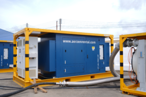
AERZEN Rental Thailand provides rental blowers with full technical support — from initial sizing and commissioning to failure diagnostics and emergency swap-out. If your plant operates critical continuous-process equipment and needs a reliable standby or replacement unit, contact our engineering team.
Contact:
- 24/7 Hotline: 098-323-2626
- Office: 038-015-488
- Email: thai@aerzenrental.com
- Website: www.aerzenrentalth.com
Rent a solution. Expect performance.
References
- ISO 10816-3:2009, “Mechanical vibration — Evaluation of machine vibration by measurements on non-rotating parts — Part 3.” ISO. Available: https://www.iso.org/standard/28190.html — [verified 2026-06-12]
- ISO 8573-1:2010, “Compressed air — Part 1: Contaminants and purity classes.” ISO. Available: https://www.iso.org/standard/46591.html — [verified 2026-06-12]
- IEC 60034-1:2017, “Rotating electrical machines — Part 1: Rating and performance.” IEC. Available: https://www.iec.ch/homepage — [verified 2026-06-12]
About the Author
Paradorn Wannasung holds a Master’s in Marketing Communication and specializes in technical content for industrial engineering audiences at AERZEN Rental Thailand. AERZEN Group, founded in Germany in 1864, manufactures positive displacement blowers, screw compressors, and turbo blowers serving global industrial markets. Paradorn translates engineering documentation into actionable maintenance guidance for plant and reliability teams.
By Paradorn Wannasung · Master’s in Marketing Communication · AERZEN Rental Thailand
Status: draft — pending editor QA before publish TEACHING_SAMPLE — anonymized case study for illustrative purposes only

✍️ เกี่ยวกับผู้เขียน
ภราดร วรรณสังข์ (Paradorn Wannasung)
Marketing Communication Specialist · นิเทศศาสตรมหาบัณฑิต (การสื่อสารการตลาดและแบรนด์)
ภราดร (Paradorn) เป็นผู้ดูแลด้านการสื่อสารการตลาดของ AERZEN Rental Thailand จบนิเทศศาสตรมหาบัณฑิต (การสื่อสารการตลาดและแบรนด์) เชี่ยวชาญด้านอุตสาหกรรม B2B ในประเทศไทย มีประสบการณ์การสร้างแบรนด์และคอนเทนต์ในกลุ่มอุตสาหกรรมของไทย
ติดต่อ: pwa@aerzenrental.com · LinkedIn
บทความที่เกี่ยวข้อง
ISO 8573-1 Class 0: วิธีวัด Oil Aerosol ด้วย ISO 8573-2 (Test Method) | AERZEN TH
Oil-Free Air ISO 857...
อ่านต่อ →
Latex Glove Manufacturing — คุณภาพอากาศสำหรับผลิตภัณฑ์ระดับ Medical Grade
เขียนโดย Paradorn Wa...
อ่านต่อ →